3D Viewports | The Grid

By the time you are reading this, using (or interacting with) a 3D viewport is something that is taken for granted, and almost considered a standard in the software ecosystem, similar to blank sheets in word text processors, cells in CSV editors. There must be handlers to move, scale, rotate (and so on) objects in the 3D scene; having powerful gpus as a standard means the 3D viewport should handle cool light, shading effects such as displaying normals, tangents, shadows, etc. However, there is something common to almost all 3D viewports that often goes unnoticed: the reference grids.
This article is focused on grid creation based on actual geometry. There are other approaches that involve texturing or fragment shaders which will (perhaps) be covered on future blog articles.
Ground reference is present in a wide variety of applications, with an emphasis on computer aided solutions. Farm machinery guided by GPS uses it, planes use it, ships use it, and so on.
If we shift towards more artistic places, drawing also uses ground reference, so it's not a surprise that 3D software also takes advantage of it. And to give the user the hint, a common solution is to display a grid where the center is the world origin, and the sides' expansion cover at least part of the ground level surface.
The idea then can be extended to serve as reference for walls, perspective methods and such, but how do we make them in the first place?
Grid generation approaches
It turns out that generating a grid in a 3D viewport is not that complicated. Well you can of course, entangle things up, but let's try and skip that for this article.
This article skips the OpenGL implementation for the final visualization. You can take a look at completed implementations at n0mad's code-lab.
First, there are a couple things to note. I probably repeat this structures and code along many articles and posts, but for the code below to make sense we have to define some data structures:
typedef struct {
    float x, y, z;
} vec3_t;

typedef struct {
    float r, g, b, a;
} col4_t;

typedef struct {
    vec3_t pos;
    col4_t col;
    ...
} vertex_t;
How you set up those inside your code, and how you handle the functions that work with them is up to you in this case. Other articles may present the insights for specific vector math functionality. Never-mind let's jump into the subject matter.
Grid using slices (lines)
Uncomplicated, easy, fast. This method was one of the latest I came up with, and had it been the other way around, I'd probably have not bothered to try investigating the rest.
As in a blank paper canvas, this way of creating a grid involves drawing one of the axis lines first, sequentially, based on a space given per line grid, and then the same for the perpendicular axis. Sure you end up having some duplicated vertices in the corners, but the results couldn't be more straight forward.
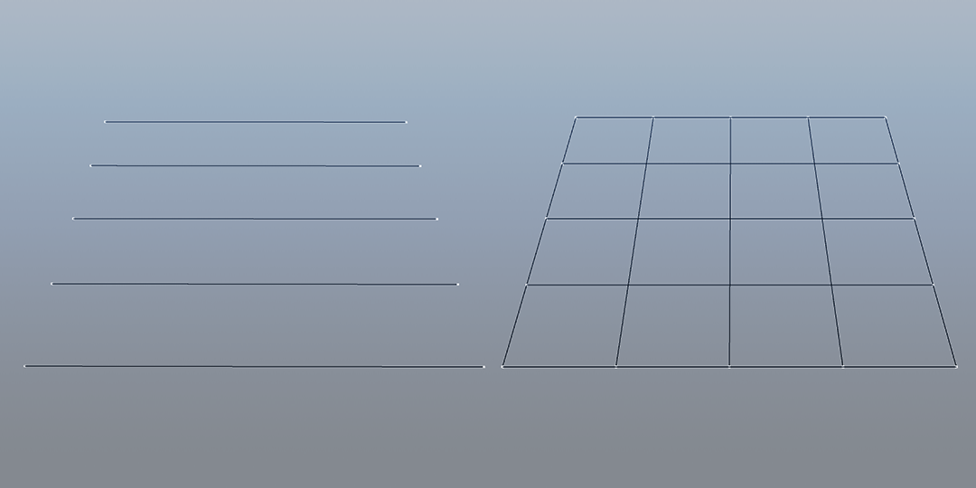
You can even add a different line color for the ones that make the grid origin.
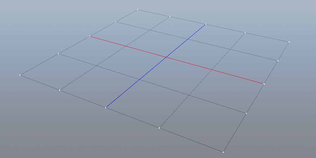
Let's take a look to the current implementation. Note that for the center lines to be colored, our slices count must be odd.
The key for this method to work in a dynamic way is that for any given axis direction:
- Calculate position along the direction axis using an offset.
- Calculate position across the direction axis using a step value in the perpendicular plane.
int grid_1d(float size, int slices, plane_axis_e plane, int ln_color) {
    /* slices must be odd */
    if (!(slices % 2)) return 1;

    float step = size / (slices -1);
    float hsize = size * 0.5f;

    /* step vec should be perpendicular to dir vec positive axis */
    vec3_t stepv, dirv;
    switch (plane) {
        case XY_AXIS:
            vec3_set(&stepv, step, 0.0f, 0.0f);
            vec3_set(&dirv, 0.0f, 1.0f, 0.0f);
            break;
        case XZ_AXIS:
            vec3_set(&stepv, step, 0.0f, 0.0f);
            vec3_set(&dirv, 0.0f, 0.0f, 1.0f);
            break;
        case YX_AXIS:
            vec3_set(&stepv, 0.0f, step, 0.0f);
            vec3_set(&dirv, 1.0f, 0.0f, 0.0f);
            break;
        case YZ_AXIS:
            vec3_set(&stepv, 0.0f, step, 0.0f);
            vec3_set(&dirv, 0.0f, 0.0f, 1.0f);
            break;
        case ZX_AXIS:
            vec3_set(&stepv, 0.0f, 0.0f, step);
            vec3_set(&dirv, 1.0f, 0.0f, 0.0f);
            break;
        case ZY_AXIS:
            vec3_set(&stepv, 0.0f, 0.0f, step);
            vec3_set(&dirv, 0.0f, 1.0f, 0.0f);
            break;
        default:
            /* no dir no step */
            printf("[SHAPES] no valid plane axis for 1d grid\n");
            vec3_set(&stepv, 0.0f, 0.0f, 0.0f);
            vec3_set(&dirv, 0.0f, 0.0f, 0.0f);
            break;
    }

    GLuint vcount = slices * 2; /* 2 verts per slice (line) */
    vertex_t *verts = (vertex_t *)calloc(vcount, sizeof(vertex_t));

    float r, g, b, a = 1.0f;
    float fac = ((slices - 1) * 0.5f);
    for (int i = 0; i < slices; i++) {
        int idx = i * 2;
        float line_offset = -hsize + i * step;

        verts[idx].pos.x = line_offset * dirv.x - stepv.x * fac;
        verts[idx].pos.y = line_offset * dirv.y - stepv.y * fac;
        verts[idx].pos.z = line_offset * dirv.z - stepv.z * fac;

        verts[idx + 1].pos.x = line_offset * dirv.x + stepv.x * fac;
        verts[idx + 1].pos.y = line_offset * dirv.y + stepv.y * fac;
        verts[idx + 1].pos.z = line_offset * dirv.z + stepv.z * fac;

        if (i == (int)((slices - 1) * 0.5f)) {
            if (!ln_color) {
                r = g = b = 0.0f;
            } else {
                r = (plane == XY_AXIS || plane == XZ_AXIS) ? 1.0f : 0.0f;
                g = (plane == YX_AXIS || plane == YZ_AXIS) ? 1.0f : 0.0f;
                b = (plane == ZX_AXIS || plane == ZY_AXIS) ? 1.0f : 0.0f;
            }
        } else {
            r = g = b = 0.5f;
        }

        verts[idx].col.x = verts[idx + 1].col.x = r;
        verts[idx].col.y = verts[idx + 1].col.y = g;
        verts[idx].col.z = verts[idx + 1].col.z = b;
        verts[idx].col.w = verts[idx + 1].col.w = a;
    }
}
That code will give us half of the work to get a complete grid on the viewport. In order to achieve such result we need to combine two 1d grids. Such accomplishment can be done by calling the grid_1d function twice, using different values for the plane axis, or by combining the efforts into a grid_2d function that does all the work inside so we can enjoy a cool grid in a simple function call.
int grid_2d(float size, int slices, plane_axis_e plane, int ln_color) {
    /* slices must be odd */
    if (!(slices % 2)) return 1;

    float step = size / (slices -1);
    float hsize = size * 0.5f;

    /* step_dir should be perpendicular to dir positive axis
     * xdirv is perpendicular direction for the grid */
    vec3_t stepv, dirv, xstepv, xdirv;
    switch (plane) {
        case XY_AXIS:
            vec3_set(&stepv, step, 0.0f, 0.0f);
            vec3_set(&dirv, 0.0f, 1.0f, 0.0f);
            /* YX */
            vec3_set(&xstepv, 0.0f, step, 0.0f);
            vec3_set(&xdirv, 1.0f, 0.0f, 0.0f);
            break;
        case XZ_AXIS:
            vec3_set(&stepv, step, 0.0f, 0.0f);
            vec3_set(&dirv, 0.0f, 0.0f, 1.0f);
            /* ZX */
            vec3_set(&xstepv, 0.0f, 0.0f, step);
            vec3_set(&xdirv, 1.0f, 0.0f, 0.0f);
            break;
        case ZY_AXIS:
            vec3_set(&stepv, 0.0f, 0.0f, step);
            vec3_set(&dirv, 0.0f, 1.0f, 0.0f);
            /* YZ */
            vec3_set(&xstepv, 0.0f, step, 0.0f);
            vec3_set(&xdirv, 0.0f, 0.0f, 1.0f);
            break;
        default:
            /* no dir no step */
            printf("[SHAPES] no valid plane axis for 2d grid\n");
            vec3_set(&stepv, 0.0f, 0.0f, 0.0f);
            vec3_set(&dirv, 0.0f, 0.0f, 0.0f);
            xstepv = stepv;
            xdirv = dirv;
            break;
    }

    GLuint vcount = slices * 4; /* 2 verts per slice (line) * 2 sets for 2d */
    vertex_t *verts = (vertex_t *)calloc(vcount, sizeof(vertex_t));

    float r, g, b, a = 1.0f;
    float fac = ((slices - 1) * 0.5f);
    float line_offset = 0;
    for (int i = 0; i < slices; i++) {
        int idx_a = i * 2;
        line_offset = -hsize + i * step;

        verts[idx_a].pos.x = line_offset * dirv.x - stepv.x * fac;
        verts[idx_a].pos.y = line_offset * dirv.y - stepv.y * fac;
        verts[idx_a].pos.z = line_offset * dirv.z - stepv.z * fac;

        verts[idx_a + 1].pos.x = line_offset * dirv.x + stepv.x * fac;
        verts[idx_a + 1].pos.y = line_offset * dirv.y + stepv.y * fac;
        verts[idx_a + 1].pos.z = line_offset * dirv.z + stepv.z * fac;

        if (i == (int)((slices - 1) * 0.5f)) {
            if (!ln_color) {
                r = g = b = 0.0f;
            } else {
                r = (plane == XZ_AXIS || plane == XY_AXIS) ? 1.0f : 0.0f;
                g = 0.0f;
                b = (plane == ZY_AXIS) ? 1.0f : 0.0f;
            }
        } else {
            r = g = b = 0.5f;
        }

        verts[idx_a].col.x = verts[idx_a + 1].col.x = r;
        verts[idx_a].col.y = verts[idx_a + 1].col.y = g;
        verts[idx_a].col.z = verts[idx_a + 1].col.z = b;
        verts[idx_a].col.w = verts[idx_a + 1].col.w = a;
    }

    /* now we start with the perpendicular side */
    GLuint vert_offset = slices * 2;
    for (int i = 0; i < slices; i++) {
        int idx_b = (i * 2) + vert_offset;
        line_offset = -hsize + i * step;

        verts[idx_b].pos.x = line_offset * xdirv.x - xstepv.x * fac;
        verts[idx_b].pos.y = line_offset * xdirv.y - xstepv.y * fac;
        verts[idx_b].pos.z = line_offset * xdirv.z - xstepv.z * fac;

        verts[idx_b + 1].pos.x = line_offset * xdirv.x + xstepv.x * fac;
        verts[idx_b + 1].pos.y = line_offset * xdirv.y + xstepv.y * fac;
        verts[idx_b + 1].pos.z = line_offset * xdirv.z + xstepv.z * fac;

        if (i == (int)((slices - 1) * 0.5f)) {
            if (!ln_color) {
                r = g = b = 0.0f;
            } else {
                r = 0.0f;
                g = (plane == XY_AXIS || plane == ZY_AXIS) ? 1.0f : 0.0f;
                b = (plane == XZ_AXIS) ? 1.0f : 0.0f;
            }
        } else {
            r = g = b = 0.5f;
        }

        verts[idx_b].col.x = verts[idx_b + 1].col.x = r;
        verts[idx_b].col.y = verts[idx_b + 1].col.y = g;
        verts[idx_b].col.z = verts[idx_b + 1].col.z = b;
        verts[idx_b].col.w = verts[idx_b + 1].col.w = a;
    }
    return 0;
}
As you can see, there's nothing fancy inside the new function. We've reduced the number of plane axis available to the user, and we have combined two loops inside a single function to generate both parts of the grid.
What it makes under the hood is to calculate the direction and step vectors for each 1d grid at the given plane axis switch. The first 1d grid is generated using the provided plane axis, and the second one is generated by calculating the perpendicular plane axis to the one given in the function parameter.
It then takes in account that we have a vertex count relation of 2 times the number of slices in a 1d grid, so here the function doubles it. Lastly in order to apply the correct data into the vertices struct array, we start at slices times 2.
Grid using indexed lines
Graphics libraries offer different ways to present the primitives into the GPU pipeline. One of them is indexed geometry, something we didn't achieve with the previous grid generation approach.
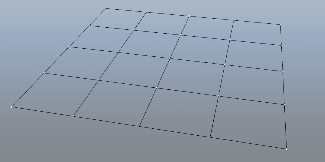
Instead of drawing the slices of the grid with just two vertices, we can take a different approach, and subdivide each line by the number of the slices parameter. This give us that the total number of vertices required for our grid is slices * slices.
Then, taking in account that we have a 2d grid, we need to run two nested loops, one around u and the other around v, being u the horizontal axis, and v the vertical one. The outer loop moves from top to bottom, and the inner loop moves from left to right.
To make the iteration possible, we generate a vertex iterator (vi) that converts the 2d position of (u,v) and converts it to 1d (the vertex in the vertex array corresponding to that coordinate):
int vi = v * slices + u;Then for each vertex we calculate the 3d position of it. Since the height is constant, that value is left as 0.0f but the other two need to be set.
The value -hsize indicates that we start the vertex position at the left-bottom edge, and we move them with the step value each time.
In this example we gave the user an option to select the plane axis where to draw the grid. Depending on their choice, the vpos will change from the Y to the Z axis.
We then have to tell OpenGL how to connect the dots, indexing them that's it. The code runs two loops, the first one generating the indices for the horizontal lines, and the second one generating the vertical ones.
int grid_2d_indexed(float size, int slices, plane_axis_e plane) {
    float step = size / (slices - 1);
    float hsize = size * 0.5f;

    // vertices
    GLuint vcount = slices * slices;
    vertex_t *verts = (vertex_t *)calloc(vcount, sizeof(vertex_t));

    for (int v = 0; v < slices; ++v) {
        for (int u = 0; u < slices; ++u) {
            int vi = v * slices + u;
            float upos = -hsize + u * step;
            float vpos = -hsize + v * step;
            switch (plane) {
                case XY_AXIS:
                    vec3_set(&_verts[vi].pos, upos, -vpos, 0.0f);
                    break;
                case XZ_AXIS:
                    vec3_set(&_verts[vi].pos, upos, 0.0f, vpos);
                    break;
                default:
                    printf("[SHAPES] invalid axis plane\n");
                    vec3_set(&_verts[vi].pos, 0.0f, 0.0f, 0.0f);
                    break;
            }

            float umap = (float)u / (slices - 1);
            float vmap = 1.0f - (float)v / (slices - 1);

            col4_t uvcol = {umap, vmap, 0.0f, 1.0f};
            verts[vi].col = uvcol;
        }
    }

    // indices
    GLuint icount = (slices * (slices - 1)) * 4;
    GLuint *inds = calloc(icount, sizeof(GLuint));

    int k = 0;
    // u
    for(int v = 0; v < slices; v++) {
        for(int u = 0; u < (slices -1); u++) {
            inds[k++] = v * slices + u;
            inds[k++] = v * slices + (u + 1);
        }
    }
    // v
    for(int u = 0; u < slices; u++) {
        for(int v = 0; v < (slices -1); v++) {
            inds[k++] = v * slices + u;
            inds[k++] = (v + 1) * slices + u;
        }
    }

    return 0;
}
Grid using triangles
This last approach I got when reading Focus on 3D Terrain Programming by Trent Polack and could be more suitable for, well terrains. But if rendered with GL_LINES then you have a multi-purpose mesh struct.
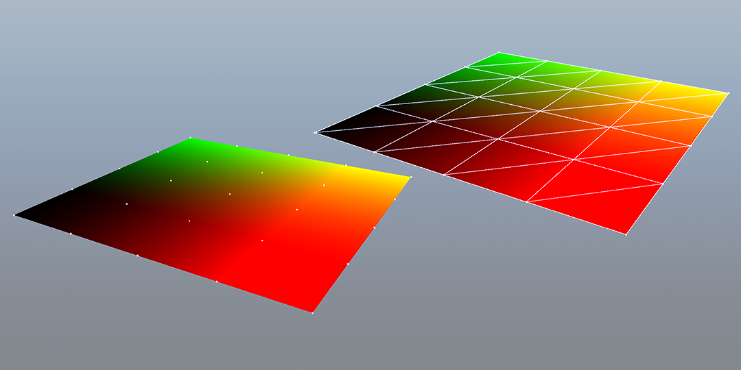
Let's call it quad-based 2d grid. It is indeed quad-based since instead of being created with the GL_LINES geometry type in mind, this approach is using the GL_TRIANGLES type, and combines two triangles to form a quad, which ends up being a slice in the grid.
The vertex placement follows the same logic as the previous grid_2d_indexed function, except in this particular case we are treating the slices as quads, so we have to close the final slice by internally updating the slices value plus one.
int quad_grid_2d(float size, int slices) {
    if (slices < 1) return 1;

    /**
     * slices are quad rows, so if we pass (ie) 4 slices
     * we expect 4 quads. We need to add 1 slice more to close the end gap
     */
    int quads = slices + 1;
    float step = size / slices;

    float hsize = size * 0.5f;

    int vcount= quads * quads;
    vertex_t *verts = (vertex_t *)calloc(vcount, sizeof(vertex_t));

    /* 2 tris per quad, 3 inds per tri */
    GLuint icount = slices * slices * 6;
    GLuint *inds = (GLuint *)calloc(icount, sizeof(GLuint));

    for (int v = 0; v < quads; ++v) {
        for (int u = 0; u < quads; ++u) {
            int vi = v * quads + u;
            float upos = -hsize + u * step;
            float vpos = -hsize + v * step;
            switch (plane) {
                case XY_AXIS:
                    vec3_set(&_verts[vi].pos, upos, -vpos, 0.0f);
                    break;
                case XZ_AXIS:
                    vec3_set(&_verts[vi].pos, upos, 0.0f, vpos);
                    break;
                default:
                    printf("[SHAPES] invalid axis plane\n");
                    vec3_set(&_verts[vi].pos, 0.0f, 0.0f, 0.0f);
                    break;
            }
            vec3_set(&_verts[vi].nrm, 0.0f, 1.0f, 0.0f);

            float ucor = (float)u / (slices - 1);
            float vcor = 1.0f - (float)v / (slices - 1);
            vec4_set(&_verts[vi].col, ucor, vcor, 0.0f, 1.0f);
            vec2_set(&_verts[vi].uvc, ucor, vcor);
        }
    }
Finally we have to generate the vertex indices again. Instead of connecting the vertices in rows and columns like in the grid_2d_indexed function, this time we are generating indices for a quad, based on two triangles:
    int ii = 0;
    for (int v = 0; v < slices; ++v) {
        for (int u = 0; u < slices; ++u) {

            /**
             * tl----tr
             * |    / |
             * |   /  |
             * |  /   |
             * | /    |
             * bl————br
             */

            int tl = v * quads + u;
            int tr = tl + 1;
            int bl = (v + 1) * quads + u;
            int br = bl + 1;

            /* triangle a */
            inds[ii++] = tl;
            inds[ii++] = tr;
            inds[ii++] = bl;

            /* triangle b */
            inds[ii++] = tr;
            inds[ii++] = br;
            inds[ii++] = bl;
        }
    }

    return 0;
}
Here's an attempt of visualizing the construction process of the mesh, directly in engine:
As you may have noticed, this approach is cool but displays no clean quad mesh in the wireframe. If we just smash the vertex and index information into the OpenGL pipeline, and select GL_LINES as the primitive type to draw, it doesn't really complete the mesh grid. Most likely it's half-working by some lucky circumstances, not the programmer's skill.
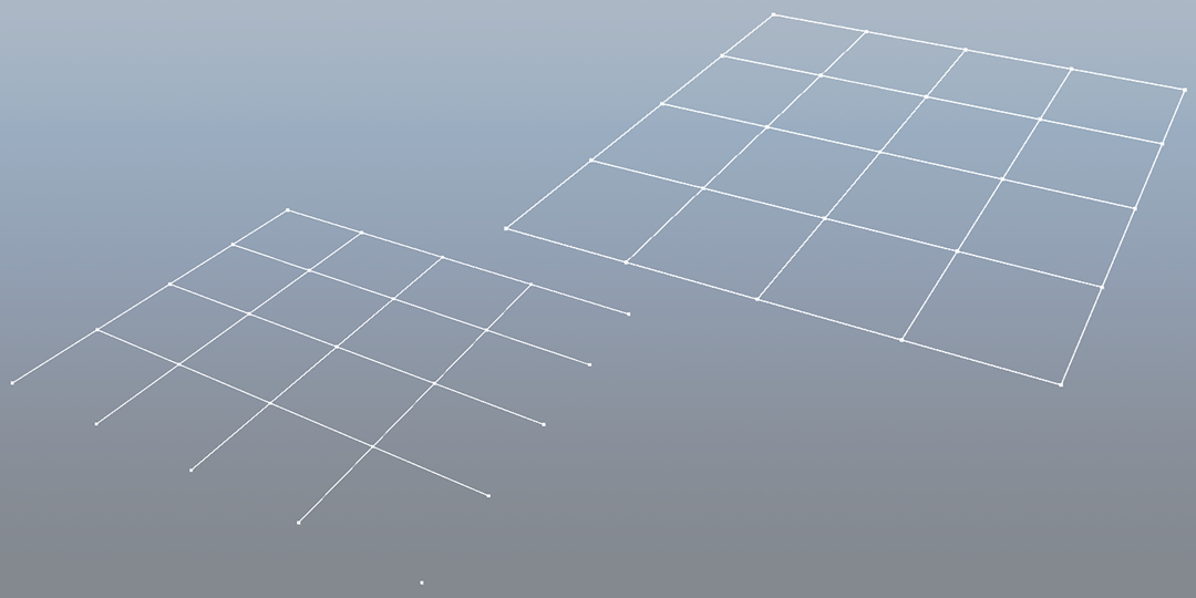
One solution would be to generate the wireframe in a shader. But that's out of the scope for this experiment. Definitely not happy with the discovery I had an idea before throwing the code away.
It appears, or at least that's what I've been able to figure out, that you can have a separate indices array for the wireframe, and choose which index array to use depending on the primitive type to draw.
int wi = 0;
for (int v = 0; v < verts_side; ++v) {
    for (int u = 0; u < verts_side; ++u) {
        if (u < slices) {
            wf_inds[wi++] = v * verts_side + u;
            wf_inds[wi++] = v * verts_side + (u + 1);
        }
        if (v < slices) {
            wf_inds[wi++] = v * verts_side + u;
            wf_inds[wi++] = (v + 1) * verts_side + u;
        }
    }
}
And there it is, the same algorithm we used for the grid_2d_indexed from the previous example (tweaked a bit since the first time I attempted to make it), generating our wf_inds to properly render a quad grid.